| |
Useful background |
You should be able to: |
3.5.1.1 Charge, current and potential difference
Electrical current as the rate of flow of charge

Potential difference as the work done per unit charge

Know that resistance is defined by

|
Charge (Q) measured in coulomb (C),
Current (I) measured in amperes or amps (A),
Potential difference (V) (sometimes called 'voltage' but use the proper term!) measured in volts (V)
Resistance (R) measured in ohms (Ω)
|
- realise that current is a resultant flow of electrons in a particular direction due to an applied P.D.and that without the P.D. the electrons are still in constant movement but these movements are random and cancel out the effects of each other.
- think of potential difference in terms of difference in 'electrical level (or height)'
- analyse a simple circuit, marking on 'potential drops' (even between strands) and calculating currents flowing in strands
- use 'croc clips' to help with practice of circuit analysis
- recall the equations from memory
- remember the 'physical meaning' of each letter
- use the correct units and their abbreviations
- manipulate the equations and perform calculations with them
- sketch graphs to represent the relationship between factors in the equations
- use the term 'direct proportionality' for a graph which goes through the origin.
- know how to measure potential difference across a component by using a voltmeter in parallel with that component
- know how to measure current through a component by using an ammeter in series with that component
- be aware of the meters available in the lab, their ranges and characteristics, advantages and disadvantages: multimeter use, dual scale moving coil meter use, shunts
- know how to check the reliability of a meter
- be able to wire up a circuit to check that current through a strand of a circuit is constant, potential is shared out in the same ratio as resistance and to determine p.d. across strands of a circuit
Look at this animation of electron behaviour in a metal filament.
V=IR Spreadsheet |
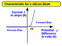
3.5.1.2 Current/voltage characteristics for:
 an ohmic conductor an ohmic conductor
a semiconductor diode
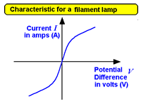
and a filament lamp
Candidates should have experience of the use of a current sensor and a voltage sensor with a datalogger to capture data from which to determine V/I curves |
|
- know how to set up the experiment to determine a characteristic curve (including the use of the voltage/current sensor equipment)
- appreciate the errors involved in such an experiment and how to minimise them.
- know how to use 'croc clips' to make measurements - computer modelling opportunity
- sketch (from memory) the characteristics of the ohmic conductor, diode and filament lamp
- explain the shape of the characteristic in terms of the device's construction and physical make-up (construction is not needed for the diode)
Questions can be set where either I or V is on the horizontal axis of the characteristic graph.
Unless specifically stated in questions, ammeters and voltmeters should be treated as ideal (having zero and infinite resistance respectively). |
| Ohm's Law understood as a special case where I is proportional to V |
|
- Quote Ohm's law as 'Ohm's Law states that the current flowing through an Ohmic resistor is directly proportional to the potential difference across its ends providing that physical conditions (such as temperature) remain constant.'
- Realise that the equation V=I R is simply used to calculate the resistance of a material as a ratio and, in all other cases than a metallic conductor under constant conditions, does NOT relate to the gradient of the graph - that is a coincidence!
Resistance is the ratio! |
3.5.1.3 Resistivity
Use of

Description of the qualitative effect of temperature on the resistance of metal conductors and thermistors (Only negative temperature coefficient (ntc) thermistors will be considered).
Applications of thermistors to include temperature sensors and resistance–temperature graphs.
|
Resistivity r

|
MS 3.2, 4.3 / PS 1.2 / AT a, b, f, g Investigation of the variation of resistance of a thermistor with temperature.
- although you don't have to recall the equation from memory
remember the 'physical meaning' of each letter
- know how to use a micrometer screwgauge and vernier calipers
- use the correct units and their abbreviations
manipulate the equations and perform calculations with them
- sketch graphs to represent the relationship between factors in the equation (including inverse proportionality!)
- relate behaviour of metals with physical properties (cross sectional area, length and how tightly are held the valence electrons of the atom).
- understand the structure of semiconductors and how temperature effects the resistivity of them.
- quote Ohm's law in words (not forgetting the proviso about temperature!) - never say simply V= IR!
- know how to use a micrometer (See Gibbs page 5)
- know how to design and carry out an experiment, mindful of minimising errors and identifying anomalies
- be aware of systematic and random errors (Gibbs pages 6-7)
- be able to estimate errors on measurements made
Resistivity Spreadsheet
|
| Superconductivity as a property of certain materials which have zero resistivity at and below a critical
temperature which depends on the material. |
Applications to include the production of strong magnetic fields and the reduction of energy loss in transmission of electric power. |
Critical field will not be assessed.
Required practical 5: Determination of resistivity of a wire using a micrometer, ammeter and voltmeter. |
3.5.1.4 Circuits
Series
 and and
parallel  resistor circuits resistor circuits
|
MS 0.3 / PS 4.1 / AT a, b, f, g Students can construct circuits with various component configurations and measure currents and potential differences.
|
- know how to work out combinations of resistors in series and in parallel
- know that a parallel resistor network has a net value of less than the value of any one resistor in that arrangement
- derive the equations for resistors in series and in parallel
- analyse a series/parallel combination circuit, marking on 'potential drops' and calculating currents flowing in strands
- wire up a practical circuit to investigate current and p.d. in combination circuits
- make use of the interactive spreadsheet. |
Recall and use of 
Energy and power in simple d.c. circuits
Application, e.g. understanding of high current requirement for a starter motor in a motor car
Conservation of charge and energy in simple d.c. circuits
The relationships between currents, voltages and resistances in series and parallel circuits, including cells in series and identical cells in parallel;
questions will not be set which require the use of simultaneous equations to calculate currents or potential difference |
Kirchhoff's laws (Kirchhoff's first law was met pre-GCSE) |
- derive E = V I t and P=I2R from known GCSE equations
- analyse circuits and find the power dissipated in any component (or the energy dissipated in a given time
- Understand that car batteries have low voltage so to provide the energy needed to ignite the petrol in a short time a high current is needed.
Interactive Spreadsheet
- understand how a potential divider can be used to supply a variable p.d.
- know and quote that 'Kirchhoff's First Law states that the algebraic sum of the currents in a circuit is zero' (charge is conserved)
- know that energy is conserved within a circuit and quote that 'According to Kirchhoff's Second Law, energy supplied by a power supply is equal to the sum of the energies of power dissipation in a circuit'. In other words the algebraic sum of the EMFs is equal to the algebraic sum of the product of the current and pd across circuit components in any ring of a circuit.
- analysis of simple circuits |
3.5.1.5 Potential divider
The potential divider used to supply variable p.d. e.g. application as an audio 'volume' control.
Examples should include the use of variable resistors, thermistors and L.D.R.'s in the potential divider. |
The use of the potentiometer as a measuring instrument is not required. |
- analysis of simple circuits
- sharing out 'voltage' in proportion to resistance across a strand in a circuit.
- Make use of the interactive spreadsheet |
3.5.1.6 Electromotive force (EMF) and terminal PD
Internal resistance r
Applications; e.g. low internal resistance for a car. |
Students will be expected to understand and perform calculations for circuits in which the internal resistance of the supply is not negligible. |
Required practical 6: Investigation of the emf and internal resistance of electric cells and batteries by measuring the variation of the terminal pd of the cell with current in it.
- perform calculations with circuits where an internal resistance of a cell is present.
- Appreciate that if the external resistance is large compared to the internal resistance the 'lot volts' will be negligible.
- define electromotive force as 'the energy given to each coulomb of charge by a battery. This is measured by a voltmeter connected across the battery terminals when it is connected in 'open circuit' (no current is flowing in the external circuit).'
- define internal resistance as 'the resistance of the battery itself within the circuit. When a battery is connected so as to drive a current through an external circuit, a drop in voltmeter reading is recorded on a voltmeter connected across the battery terminals. This is termed 'lost volts'. The volts are not really lost but are the potential drop across the internal resistance. Therefore this drop can be used to calculate the value using 'Lost volts = I t'
Make use of the interactive spreadsheet. |


