
 |
Electronics: Multiplexers (MUX) An electronic multiplexer makes it possible for several signals to share one device or resource. It is complemented by a demultiplexer - a device that takes a single input signal and selects one of many data-output-lines to send the signal to.
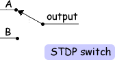
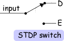
In physics electricity, the circuit diagram of an equivalent circuit would be the STDP switch. (See the diagram on the left). The same symbol is used for the demultiplexer. The only difference is the number of input/output lines.
Which input is to be connected to the output (or output from the input for the DEMUX) is selected using the select line. A multiplexer of 2n inputs has n select lines.
The 'S' is given a subscript number - lowest being 0. This is really for situations where you need more than one S value - however it is good practice to give S a subscript anyway. Click here for the 2 input multiplexer. Often, a multiplexer and demultiplexer are combined together into a single piece of equipment, which is usually referred to simply as a "multiplexer". Both pieces of equipment are needed at both ends of a transmission link because most communications systems transmit data in both directions. Multiplexers are used to increase the amount of data that can be sent over a network within a certain amount of time and bandwidth.
The cost of implementing separate channels for each data source is more expensive than the cost and inconvenience of providing the multiplexing/demultiplexing functions.
|
Follow me...
|
 A multiplexer is also called a data selector.
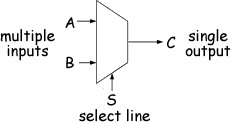 The symbol for a multiplexer is an isosceles trapezoid with the longer parallel side containing the multiple input pins and the short parallel side containing the single output pin.
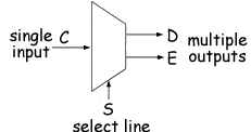
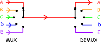 Multiplexers can be useful in reducing costs within a data transfer system. By connecting a multiplexer(MUX) and a demultiplexer (or DEMUX) at either end of a single channel, several signal sources can make use of one channel. The animated gif on the right demonstrates this.


Cyberphysics - a web-based teaching aid - for students of physics, their teachers and parents....
