
 |
|
 Electronics: Adder
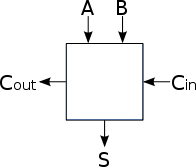 The symbol for an adder is a square - some people put a large 'add' sign in the middle of it to denote 'adder'.
 A |
B |
Y1 |
Y0 |
0 |
0 |
0 |
0 |
0 |
1 |
0 |
1 |
1 |
0 |
0 |
1 |
1 |
1 |
1 |
0 |
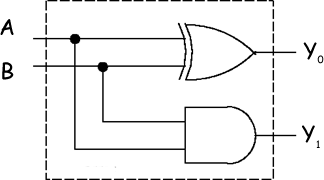
Looking at the truth table we can see that:
- The least significant bit (LSB) of the output, Y0, is the result of XOR-ing the inputs.A and B.
- The carry bit, Y1, results from AND-ing A and B.
Example: 3 + 1 = 4
| Y2 | Y1 | Y0 | |
|
1 |
1 |
3 |
|
0 |
1 |
+1 |
1 |
1 |
|
(carry) |
1 |
0 |
0 |
(result) 4 |
The result of the LSB addition results in a 0 result and a carry of 1. That carry then has to be added to the next bit addition column, resulting in another 0 result and a further carry that will become the carry bit.
Full Adder
When two (or more) bit binary numbers are added, the problem is a little more complicated. Instead of just having a 'carry' to output we have a 'carry' which must be added into the sum.
Adder units need to be able to have a carry bit input as well as an output.
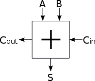
The truth table for the full adder (with carry input) is given below.
(inputs are yellow to help you see the pattern)
A |
B |
Cin |
Cout |
S |
0 |
0 |
0 |
0 |
0 |
0 |
0 |
1 |
0 |
1 |
0 |
1 |
0 |
0 |
1 |
0 |
1 |
1 |
1 |
0 |
1 |
0 |
0 |
0 |
1 |
1 |
0 |
1 |
1 |
0 |
1 |
1 |
0 |
1 |
0 |
1 |
1 |
1 |
1 |
1 |
- The carry-out bit is 1 if o both A and B are 1, or one of A and B is 1 and the input carry is 1.
- The sum bit S is 1 if an odd number of the three inputs is on, i.e., S1 is the XOR of the three inputs.
Note that the full adder can be constructed from two half adders and an XOR gate.
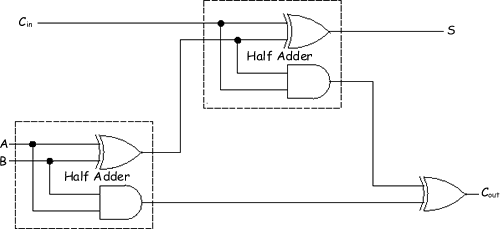
This diagram can be simplified into 'boxes' for the logic gate representations.
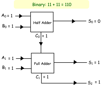
Example: 3 + 3 = 6
Click here for a page showing the steps in designing a simple adder.
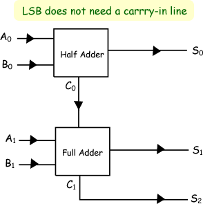
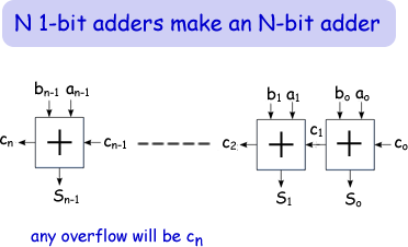
N-bit adder
Adders for large binary numbers can be constructed by cascading full adders. The carry-bit is said to ripple from one stage to the next.
One major drawback of this circuit is that the 'carry information' has to propagate through all stages. It is an electrical path from A0 and B0 to S4 in the diagram below. This electrical path moves through 2N-1 gates in an N-bit adder. This may lead to long delays before the output stabilizes. The problem can be overcome by more complex carry computations that is beyond the scope of this site.

Subtraction using adders - click here

Follow me...
![]()
![]()


Cyberphysics - a web-based teaching aid - for students of physics, their teachers and parents....
