Questions on EMF and internal resistance
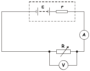
Q5. A battery of EMF  and internal resistance r is connected in series to a variable resistor R and an ammeter of negligible resistance. A voltmeter is connected across R, as shown in the diagram.
(a)
(i) State what is meant by the EMF of the battery.
The EMF of the battery is the electrical energy produced per unit charge  [- it is equal to the potential difference/voltage across terminals of the battery when there is no current being drawn from it – or the reading on the voltmeter when connected on open circuit]
(ii) The reading on the voltmeter is less than the EMF. Explain why this is so.
The reading on the voltmeter gives the potential difference across the external circuit. When a current flows some of the EMF is used to drive that current through the battery . This results in voltage being 'lost' across the internal resistance as this is not measured on the instrument.
(3)
(b) A student wishes to measure and r. Using the circuit shown above, the value of R is decreased in steps, and at each step the readings V and I on the voltmeter and ammeter respectively are recorded.
These are shown in the table below.
reading on voltmeter/V |
reading on ammeter/A |
8.3 |
0.07 |
6.8 |
0.17 |
4.6 |
0.33 |
2.9 |
0.44 |
0.3 |
0.63 |
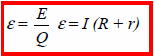
(i) Give an expression relating V, I, and r.
 = V + Ir
(ii) Draw a graph of V (on the y-axis) against I (on the x-axis) on graph paper.
Marks were allocated as follows:
correctly labelled axes (with units)
correct plotting
best fit straight line
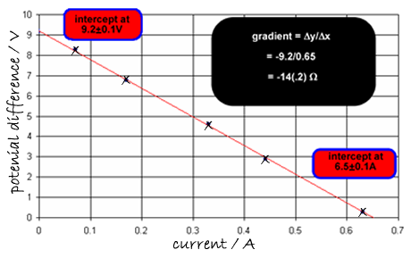
(iii) Determine the values of and r from the graph, explaining your method.
= V + Ir can be rearranged to be the equation of a straight line
V = -rI + if we compare this to the equation for a straight line
Y = mx + c we can see that
Y is V - the reading on the voltmeter (external potential difference)
x is I - the ammeter reading – the current
-r is m - the gradient of the graph (one mark for the negative sign) = -14 
so r = 14
is c - the intercept on the y axis = 9.2 V
(9)
(Total 12 marks)


