
 |
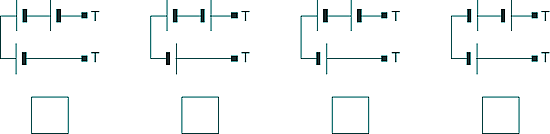
GCSE Standard Questions: Electric Circuits Q4. The diagram shows the inside of a battery pack designed to hold three identical 1.5 V cells.
(a) Tick the one of the arrangements below that would give a 4.5 V output across the battery pack terminals T.
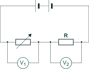
[1 mark] (b) The following diagram shows a variable resistor and a fixed value resistor connected in series in a
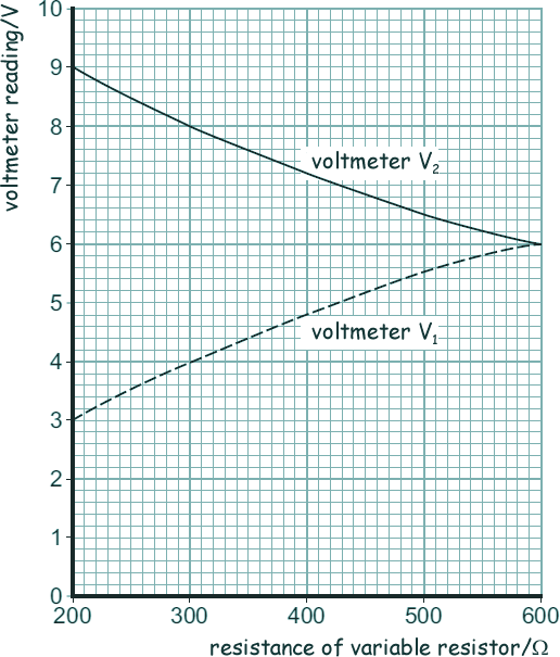
Complete the diagram above to show how an ammeter would be connected to measure the current through the circuit. Use the correct circuit symbol for an ammeter. [1 mark] (c) The variable resistor can be adjusted to have any value from 200Ω to 600Ω . The following graph shows how the reading on voltmeter V1 and the reading on voltmeter V2 change as the resistance of the variable resistor changes.
[2 marks]
[2 marks]
[3 marks] (Total 9 marks)
|
Follow me...
|


Cyberphysics - a web-based teaching aid - for students of physics, their teachers and parents....
