
 |
Potential Divider Circuits Voltage is 'shared out' across resistors according to their resistance value. The bigger the resistance of a resstor compared to others sharing the voltage, the bigger the share it will get. In a practical situation we can make use of this potential division to produce a variale power supply from one of fixed voltage. To do this we can use a potentiometer.
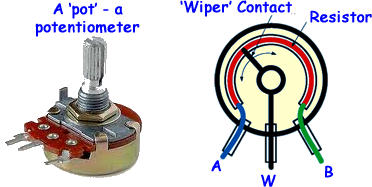
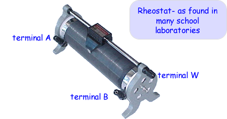
A potentiometer is often referred to by electronic engineers as a 'pot', is a three-terminal resistor with a sliding contact that can be used as an adjustable voltage divider. If only two terminals are used, one end (A or B) and 'the wiper'(W), it acts as a variable resistor or rheostat. Potentiometers are commonly used to control electrical devices such as volume controls on audio equipment. They are operated by a mechanism that means that can be used as position transducers, for example, in a joystick. In school you will often use a rheostat to produce a potential divider circuit.
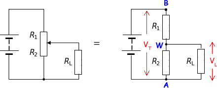
Remember that voltage is shared by resistors. RL (load resotance) will therefore get the same voltage as R2. If the slider is half way the voltage across RL will be half the batter potential. The ratio of voltgae VT to the total resistance will be the same as the voltage VL to the load resistance.
Therefore if you only require 6V but have a 12V battery, you can 'tap off' the required 6V by using a potential divider ('pot') arrangement with the 'wiper' at a half way position - by making RL half of RT.
|
Follow me...
|


Cyberphysics - a web-based teaching aid - for students of physics, their teachers and parents....
