
 |
The Breadboard Why on earth do we call it a breadboard?
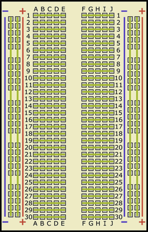
The Breadboard - what is it used for?The breadboard allows you to test circuits without having to solder components into a circuit and without having to use loads of connecting wires! It has little connection holes with stips of conducting metal connecting them underneath (either as 'power rails' or 'terminal strips'). The tops of the metal rows on the underside have little clips that hide under the plastic holes. Each metal strip and socket is spaced with a standard pitch of 0.1" (2.54mm). These clips allow you to stick a wire or the leg of a component into the exposed holes on a breadboard, which then hold it in place, making a good electrical connection. The underside is then covered with an insulating material so that you do not 'short out' the connection strips.... or the power rails. The power rails are connected to the battery via a wire. It is important that you connect the battery the correct way round. Sometimes a set of terminals is permanently connected to the power rails so that you can just 'plug in' the battery pack. There are several stages of complexity and size of breadboard - but they all have power rails and terminal strips.
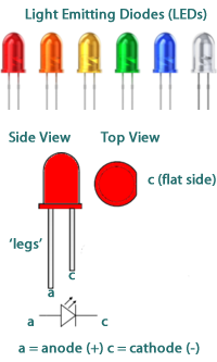
Electrical components have 'legs' - conducting wires - usually two - sometimes more ('chips' have many more!) You simply push the component's 'legs' into the holes on the board and they make contact with connecting strips. By putting the 'legs' from two components into different holes in the same 'strip' you make an electrical connection between them.
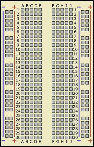
It is therefore important that you make a diagram of your circuit before you start to 'play around' with components. You then use that circuit diagram to put the components onto the board in the right places. You can use the letters and numbers to plan exactly where to place connecting wires - any component that has the same strip number as another will be connected to it!
|
Follow me...
|
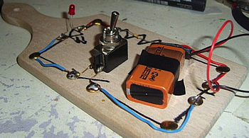 Many years ago, when electronic components were big and bulky, people would fix components to a piece of wood by nailing in a few nails or thumbtacks to wind the wires around - this later resulted in premade boards for 'wire wrap'. This use of a board gave a portable platform to build circuits on. Without the platform, attampting to move connected components resulted in disconnections and shorted wires and components.
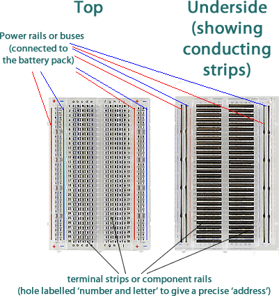


Cyberphysics - a web-based teaching aid - for students of physics, their teachers and parents....
