 sing a Multimeter in Electronics Experiments
 Let's set up some breadboard circuits and practice using the multimeter to make some measurements!
Potential Difference (Voltage) measurements:
Build the circuit shown below using prototype board
and four 10 kΩ
resistors:
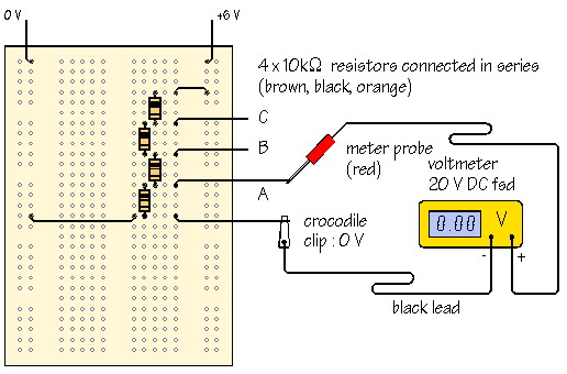
Using the multimeter as a voltmeter, measure the power supply voltage and
then measure the voltages at points A, B and C.
As the four resistors are connected in series, making a chain known as a
potential divider, or voltage divider, the
total voltage is shared between the four resistors and, allowing for tolerance,
each resistor receives an equal share - so the reading at B should be twice that at A (and a quarter of the supply voltage) - and the one at C - three times that at A.
Now, modify the circuit, replacing one or more of the 10 kΩ resistors with 1 kΩ or 100 kΩ values.
Are the
results as you expect?

The diagram below shows a light
sensor circuit built in a similar way:
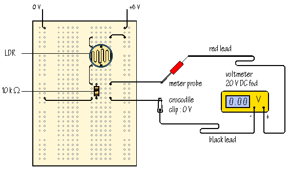
The circuit uses an LDR, or light dedpendent resistor.
The resistance of the LDR changes with illumination.
In the dark, the resistance
is high, up to 1 MΩ or more.
When light shines
on the LDR, the light energy increases the number of charge carriers available
to transfer current, and the resistance falls.
In bright light, the resistance
can be as little as 100 Ω.
2. Resistance measurements:
Remove the LDR from the circuit and measure its
resistance, as follows:
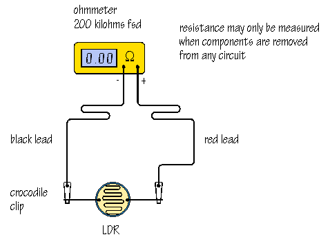
To get the multimeter to function as an ohmmeter, you will need to select a
resistance range.
With a switched range meter, the 200 kΩ position is usually suitable.
You will see the
resistance measurement change as the light level changes.
Covering the LDR with
your hand increases the resistance of the LDR.
If the meter reads  this means that the resistance is more than the maximum
which can be measured on this range and you may need to switch to a new position,
2000 kΩ, to take a reading.
this means that the resistance is more than the maximum
which can be measured on this range and you may need to switch to a new position,
2000 kΩ, to take a reading.
3. Current measurements:
The diagram below shows a prototype board (Breadboard) set up for
the measurement of current:
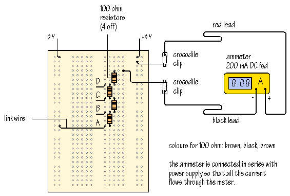
Note that the current must flow through the ammeter in order to
reach the circuit.
Take a reading of the current with the link wire to 0 V in position A.
Write down the current value you observe:
 A:
A:
Take new readings after moving the link to positions B, C and D:
|
B: |
C: |
D: |
Don't forget to write in the measurement units of your answer.
As the resistance is reduced, current increases.
Calculate the current
expected in each case using the Ohm's Law formula:
V = IR
Small variations, up to ±5%, can be attributed to the tolerance of the
resistors.
Much of the information and some of the images in this topic were taken from doctronics.co.uk - a brilliant, now defunct site that I used to direct my students towards. I have been unable to find out what happened to this site - but gladly I had saved some of the information for use in my lessons... and I now share them with you!


