
 |
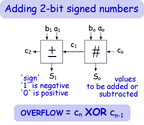
Subtractor: Adding signed numbers Subtraction is simply adding a positive number to a negative one. Therefore to subtract with 'adders' electronically we must have a way of puting a postive or negative sign before the numbers we are adding together. When we input code into a computer we have to stick to binary input - high or low signals. We do not have a special signal for positive and negative. We have to enter a high or low. To give 'signs' to a binary number we reserve the MSB (most significant bit) for that purpose. To represent a positive binary number we make the MSB (most significant bit) low (a '0'). To represent a negative binary number we make the MSB high (a '1'). See this page in the cybercomputing to understand how negative numbers are represented using complementarity.
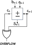
If the circuit is used to add numbers that are of too many digits the value will interfer with the sign and give the wrong answer. Consider the highest adder - the one that represents the sign.
So, you get an overflow if either the carry in OR carry out is high but not if neither or both is not. That is an XOR relationship (see logic gates).
You can therefore use the XOR as a conditional inverter - inverting the 'sign' bit if it has been corrupted by overflow. This is used in the circuit below.
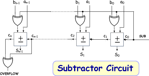
Binary number B (bn-1....b0) is to be subtracted from A (an-1....a0). To do this the circuitry changes the signals from B into the two's complemetary form by cleverly using XOR gates. ------------------------------------------------ When B is to be subtracted from A the SUB line goes high (1). This '1' then becomes one of the inputs into an XOR used as a comparitor. If the 'b input' line is high it means that both inputs to the XOR are high. Therefore the XOR output will be low. This means that the 'b input' has been switched. If the 'b input' line is low it means that only one input to the XOR is high. Therefore the XOR output will be high. This means that the 'b input' has been switched. The '1' on the sub line becomes the carry in for the adder array. Therefore as well as switching the digits the circuit adds 1. ------------------------------------------------ When B is to be simply added to A the SUB line is low (0). This '0' then becomes one of the inputs into an XOR used as a comparitor. If the 'b input' line is low it means that both inputs to the XOR are low. Therefore the XOR output will be low. This means that the 'b input' has been not been switched. If the 'b input' line is high it means that only one input to the XOR is high. Therefore the XOR output will be high. This means that the 'b input' has been not been switched. The '0' on the sub line becomes the carry in for the adder array. Therefore when in add mode it doesn't switch the digits or adds 1 to the sum - it simply adds!. |
Follow me...
|


Cyberphysics - a web-based teaching aid - for students of physics, their teachers and parents....
