Electronics: Transistor
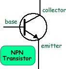
Transistors can be regarded as a type of switch. The diagram on the right shows the symbol of an NPN transistor. There are hundreds of transistors which work at different voltages but all of them fall into two categories: NPN and PNP. Most circuits use NPN - that is why most examination boards specify that they are to be used in questions.
In a bipolar transistor:
A MOSFET (Metal Oxide Semiconductor Field Effect Transistor) is a 3-lead device, the lead names being source, drain and gate. Example Circuit:
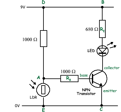
It therefore works like a switch - instead of being manually pressed like or 'normal' switch - the transistor 'switch' requires a minimum voltage across the base emitter. The resistor RE is present to protect the transistor as transistors can be easily damaged by too high a current flow. Transistors are often used in conjunction with transducers. The resistance of the transducer changes according to physical conditions. Therefore a change in temperature or light intensity can produce that shift in voltage distribution that will activate the transistor.
Under bright light the resistance of the LDR is very low - when it is in the dark it is high. Therefore the LDR will get most of the voltage, across the strand DE of the circuit, when the LDR is in the dark. This voltage will then 'switch on' the transistor and make the LED light up. In bright light the LED would be off. This could be used in an automatic lighting circuit. For example: lighting up EXIT signs in a cinema when the lights are low. This would have the advantage of saving energy when the main lights are on by automatically switching the sign lighting off.
|
Follow me...
|


 Transistors are essential electronic components in many circuits and are sometimes used to amplify a signal.
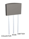
 Transistors are manufactured in different shapes but they all have three connectors(legs). You have to be sure that you identify the legs correctly when you connect a transistor into a circuit.
 In the diagram on the right the LDR and resistor form a potential divider. there is no manual switch to close.


