
 |
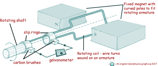
A Simplified A.C. Generator
This is called electromagnetic induction.
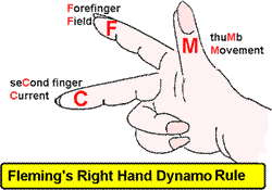
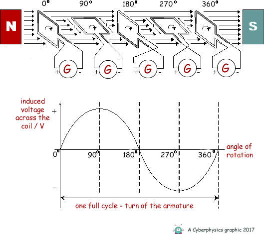
The above diagram is a very simplified a.c. generator. The rotating coil is usually of many turns of wire wrapped around a structure and the whole section of the motor is called the armature. If the wire armature is part of a complete circuit, the induced potential difference will generate an electrical current in the circuit. The two slip rings and armature are fixed so that they rotate in tandem with the shaft as it is turned. Fixed carbon brushes are not 'brushes' like you brush your hair with. They are called brushes because of the type of electrical contact they make - they brush against the shaft as it turns. They electrically connect the armature to the external circuit throughout the rotation. They 'brush' against the slip rings maintaining an electrical connection to the circuit without causing the circuit wires to wrap around the shaft. Armature position affects the rate of cutting of flux linesWhen the armature is at the vertical position the flux lines are parallel to the coil wire. That means that no magnetic flux is cut and hence no induced p.d. and therefore no induced current. As the armature rotates to the horizontal position, the rate of cutting of magnetic flux increases and the induced p.d. and therefore current increases until its maximum value at the horizontal position. As the armature continues on its rotation, the rate of cutting of magnetic flux decreases until at the vertical position it is zero again. We have now done half a turn of the coil. Using Fleming's Right Hand RuleThe direction of the induced current can be determined from Fleming's Right Hand rule.
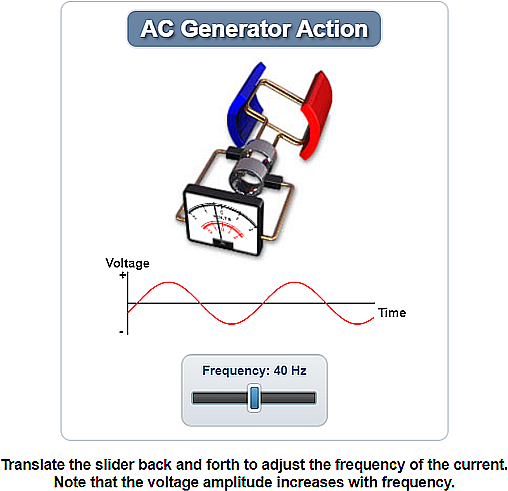
The second half of the rotation of the coilThe current increases as the coil rotates until upon reaching the horizontal position again, the induced current is maximum, but the direction of the induced current flowing through the external circuit is now reversed. The direction of the induced current (which flows through the external circuit) keeps changing depending on the orientation of the armature. This induced current is known as alternating current as in each half of the cycle the flow of current alternates its direction of flow. The current is positive (+) in one direction and negative in the other (-). The smooth rings play a critical role in the generation of alternating current. The faster the coil rotates the shorter the time period of rotation - but also the faster the rate of flux cutting so the greater the maximum p.d. produced (and therefore curent flowing in the wire). This could be an ideal question for examiners to ask about!
Here is an interactive Java applet for you to look at:
|
Follow me...
|

 Here is a link to a


Cyberphysics - a web-based teaching aid - for students of physics, their teachers and parents....
