The PQRST Heart Trace

An ECG will give a trace of a healthy heart that looks like the graph below. Each trace is a single heartbeat and therefore lasts about 0.8 seconds.
The main features of the trace are labelled as P, Q, R, S and T according to convention.
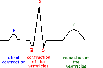
The "P" wave corresponds to atrial depolarisation and contraction.
The "QRS" complex relates to the depolarisation and contraction of the ventricles, it is much larger than the "P" wave due to the relative muscle masses of the atria and ventricles - and masks the repolarisation and relaxation of the atria.
The repolarization and relaxation of the ventricles can be seen in the form of the "T" wave, the repolarisation of the atria being masked by the "QRS" complex.
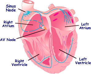 The contraction of cardiac muscle is regulated in a centre located in the right atrium known as the sinus node.
Cardiac muscle cells have a special property: they spontaneously depolarize at various rates (i.e. the charge of their membranes changes at a given rate without external stimuli). The resultant coordinated contraction leads to the ECG waveforms that need to be known for the examination.
Timing is important – it shows whether the heartbeat is normal of not!
You should know the timings:
ECG segment: |
P |
PQ |
QRS |
Normal range/s |
wave less than 0.12 |
0.12 - 0.22 |
less than 0.10s |
and that the peak pd is about 1 mV.
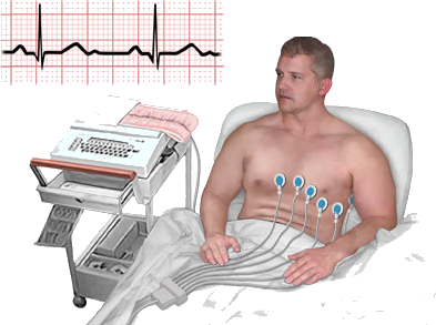 To measure and display an ECG waveform, the pd between two chosen points on the body surface must be amplified from about 1 mV to about 1 V. The allows it to be displayed on an oscilloscope, a chart recorder or a computer VDU screen.
The amplifier circuit must have the following characteristics:
High voltage gain - Its voltage gain (output/input ratio) must be of the order of 1000 over a frequency range up to about 20 Hz. Beyond this frequency, unwanted signals due to muscle activity or from the mains supply must be filtered out.
Uniform frequency respose across the full range - Its frequency response should be even across the frequency range otherwise the output voltage from the amplifier will be distorted.
High input impedance - A high input impedance is vital otherwise most of the input pd will be lost due to body and contact resistance where the electrodes are on the skin. You should be aware that contact resistance is lowered as much as possible by using a conducting paste between the electrode surface and the skin. However, the remaining resistance due to body fluids can be as much as 1000
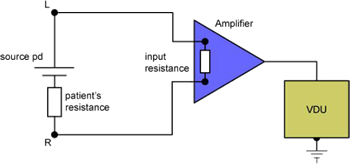
The input resistance of the amplifier and the patient's electrical resistance form a potential divider so the 'source' pd (the pd from the biopotential between the L and R of the body) will be split in the same ratio as the two resistances. If the input resistance is not much higher than the patient's resistance, the input pd to the amplifier will be roughly half that of the source pd. We therefore need the input resistance to be many times greater so that the p.d. we have to amplify is as large as possible.
Low noise - The amplifier must have a high signal-to-noise ratio otherwise the output signal can be masked by random electrical signals generated in the amplifier itself.
Click here for additional resources


