Physics 8463 - 4.2 Electricity

4.2.1 Current, potential difference and resistance

Helpful pages

4.2.1.1 Standard circuit diagram symbols

Circuit diagrams use standard symbols.

You should be able to draw and interpret circuit diagrams drawn with these.


Learn the symbols properly!

Circuits are drawn as a series of horizontal and vertical lines. There are no diagonals, curved lines or wavy lines.

Symbols are always put 'within' a vertical or horizontal line. They are never drawn 'in a corner'.

Use a ruler to draw the lines - don't leave 'gaps' - make the circles about the same size.

Aim to make your diagram look neat and 'professional'.

4.2.1.2 Electrical charge and current

For electrical charge to flow through a closed circuit the circuit must include a source of potential difference.

Electric current is a flow of electrical charge.

The size of the electric current is the rate of flow of electrical charge.

Charge flow, current and time are linked by the equation:

charge flow = current × time

Q = It

This equation is NOT given on the Physics equation sheet - you need to know it, what the letters mean and are measured in!

Q = charge flow, in coulombs, C

I = current, in ampères, A (amp is acceptable for ampère)

t = time, in seconds, s

A current has the same value at any point in a single closed loop.

 
4.2.1.3 Current, resistance and potential difference

The current (I) through a component depends on both the resistance (R) of the component and the potential difference (V) across the component.

The greater the resistance of the component the smaller the current for a given potential difference (pd) across the component.

Questions will be set using the term potential difference rather than 'voltage'. You will gain credit for the correct use of either potential difference or voltage.

Current, potential difference or resistance can be calculated using the equation:

potential difference = current × resistance

V = IR

This equation is NOT given on the Physics equation sheet - you need to know it, what the letters mean and are measured in!

V = potential difference , in volts, V

I = current, in ampères, A (amp is acceptable for ampère) R = resistance, in ohms, Ω


Required practical activity 3:

Use circuit diagrams to set up and check appropriate circuits to investigate the factors affecting the resistance of electrical circuits.

This should include:
the length of a wire at constant temperature
combinations of resistors in series and parallel.

 
4.2.1.4 Resistors

You should be able to explain that, for some resistors, the value of R remains constant but that in others it can change as the current changes.

The current through an ohmic conductor (at a constant temperature) is directly proportional to the potential difference across the resistor.

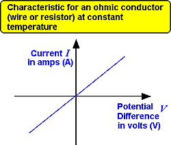
This means that the resistance remains constant as the current changes.

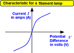
The resistance of components such as lamps, diodes, thermistors and LDRs is not constant; it changes with the current through the component.

The resistance of a filament lamp increases as the temperature of the filament increases.

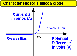
The current through a diode flows in one direction only. The diode has a very high resistance in the reverse direction.

The resistance of a thermistor decreases as the temperature increases.

The applications of thermistors in circuits eg a thermostat is required.

The resistance of an LDR decreases as light intensity increases.

The application of LDRs in circuits eg switching lights on when it gets dark is required.

You should be able to:

explain the design and use of a circuit to measure the resistance of a component by measuring the current through, and potential difference across, the component

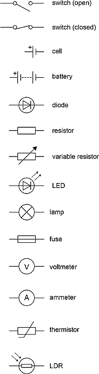
draw an appropriate circuit diagram using correct circuit symbols.

Investigate the relationship between the resistance of a thermistor and temperature.

Investigate the relationship between the resistance of an LDR and light intensity.

use graphs to explore whether circuit elements are linear or non-linear and relate the curves produced to their function and properties.

Required practical activity 4:

Use circuit diagrams to construct appropriate circuits to investigate the I–V characteristics of a variety of circuit elements, including a filament lamp, a diode and a resistor at constant temperature.

The current/PD graphs are called the characteristic curves.