| 3.7.4.1 Capacitance |
Definition of capacitance
Use of  |
I suggest you revise this section after you have revised electric fields
You need to be able to carry out calculations using this equation.
Explain the effect of varying two of the variables on the third one.
Recognise the circuit symbols for polarised and non-polarised capacitors.
Explain the practical differences between the two and suggest possible practical applications for each.
|
| 3.7.4.2 Parallel plate capacitor |
Dielectric action in a capacitor
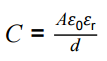
Relative permittivity and dielectric constant.
Students should be able to describe the action of a simple polar molecule that rotates in the presence of an electric field. |
Practical: You have been shown electrolytic and non-electrolytic capacitors of widely varying capacitances (we have some very large caps. retrieved from an old amplifier!)
See animation on a variable capacitor's design.
See the animation on charging a capacitor.
PS 1.2, 2.2, 4.3 / AT f, g Determine the relative permittivity of a dielectric using a parallel-plate capacitor.
Investigate the relationship between C and the dimensions of a parallel-plate capacitor eg using a capacitance meter. |
| 3.7.4.3 Energy stored by capacitor |
Derivation and use of
So E = ½ Q V = ½ C V2 = ½ Q2/ C and interpretation of area under a
graph of charge against p.d. |
Derive the equation using the Q/V graph as a basis.
Explain why the energy stored by a capacitor is half that provided by the supply in charging it (ie ½ QV compared to QV)
Refer to integral as area under graph and show that the units are consistent with work done ie energy.
|
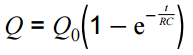
| 3.7.4.4 Capacitor charge and discharge |
Graphical representation of charging and discharging of capacitors through resistors.
Corresponding graphs for Q, V and I against time for charging and discharging.
Interpretation of gradients and areas under graphs where appropriate.
time constant = RC Calculation of time constants including their determination from
graphical data
Quantitative treatment of capacitor discharge 
Time to halve, T½ = 0.69 RC
Candidates should have experience of the use of a voltage sensor and datalogger to plot discharge curve for a capacitor.
Use of the corresponding equations for V and I. Quantitative treatment of capacitor charge,
|
Calculate what % discharge has occurred after time RC.
Derive the straight line form of the exponential decay equation (not on syllabus but good for the soul.)
Find values of R or C from graphical data.
Practical: Should know how to describe an experiment where you set up a capacitor discharge circuit using an analogue V.
Task: plot a straight- line graph to find accurate value for C.
Choose your own resistor value (need to be able to interpret resistor colour codes) by applying the RC value.
Then use datalogger with V blue box to plot ongoing exponential discharge graph and then use software to plot best fit line and find value of C.
Required practical 9: Investigation of the charge and discharge of capacitors. Analysis techniques should include log-linear plotting leading to a determination of the time constant, RC |